Deliver to BAHRAIN
IWe're committed to serving you - delivery schedules may be impacted
I1 Day DeliveryDeliver to BAHRAIN
IWe're committed to serving you - delivery schedules may be impacted
I1 Day Delivery


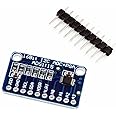
🚀 Elevate Your Projects with Precision!
The HiLetgo ADS1115 is a 16-bit, 4-channel I2C analog-to-digital converter designed for high precision and versatility. It features a programmable gain amplifier, operates within a wide voltage range of 2.0V to 5.5V, and supports a programmable data rate of 8sps to 860sps, making it an essential tool for developers using Raspberry Pi and Arduino.
M**M
Works fine, OK product
great value
S**K
Using this ADC is about as easy as it gets.
I'm using this in an old 1938 Philco radio I've converted to a juke box. It plays old mp3 files from the 1930's. I'm using it with a Raspberry Pi Zero. I use this to read a pot set up to look like a radio tuning dial. Just connect power, ground, and the tap from the pot. Connect the I2C lines to the Raspberry PI and off you go. I use another pot for a volume control. At first I was confused because the volume was not linear. I had to turn the pot about half way before the volume changed. Then I realized the pot was a "linear taper". But the ADC was doing just what it should. It was easy to program and read the values with the available python libraries. Very easy to use.
N**N
Not aligned correctly - Seller refunded without being asked.
So this is an excellent board; (I have several) but one of the boards that I have came with the ADC chip not correctly aligned, thus the two middle AI inputs do not work.Also, this is a knockoff of the Adafruit board, and if you use the Adafruit library, the AI inputs are backwards. I've verified that the Adafruit boards are indeed correct which means that this board has a mistake in it. The inputs work, but they are reversed from the silkscreen labels.-- UPDATE:Seller reached out and offered a replacement or refund without me asking. They also indicated that they will try to update the backwards silkscreen on the board. I updated my review to reflect great customer service.
S**N
Works as intented
Great module, will buy more
A**R
Accurate, programmable gains, sample size and modes of operation.
I love this little board. You don’t have to use all its features to appreciate it.You can hook up to 4 of them on an I2C bus. I ended up running mine at 3.3V out of paranoia to ensure the data and clock signal never exceeds the raspberry pi’s voltage threshold.It has many modes to take individual measurements or comparison measurements, including hardware triggers to take measurements.Internally it is taking samples in the gHz range and averages them to the sample frequency size you set it to take. The programmable gain is very useful if you overscale your voltage divider to protect your circuit.Internally it uses one Analog to Digital Converter but uses a multiplexer (MUX) to switch or connect the 4 measuring pins to it. This ensures consistency in all measurements. However, you can’t read all pins continuously if you want to use the fastest continuous measurement mode reading registers for latest results. You can easily switch to measure other pins but will need to kick off your continuous sample mode when done. Alternatively, you can get 2 boards set different addresses and kick off both in continuous mode.Single samples are plenty fast and do save power. However, I am regulating current and voltage to exact decimal points in real time and can change dynamically
C**E
Chip is actually ADS1015
Board came loaded with ADS1015 chip. This is difficult to figure out until you start running the board. It is a 12-bit ADC, otherwise functions the same.
J**D
Poor Assembly Quality, DOA
I had hoped that this would be a minimal-effort way to add an ADC to my Raspberry Pi, but unfortunately the device came with an assembly error (see photo). The ADC was skewed when it was soldered, so some of the pins bridge pads, making the device unusable. I was able to repair it by completely desoldering and resoldering the ADC, but to me the entire purpose of these products is to avoid soldering.
J**D
Last two addresses --> cut the ADDR pulldown
Don't forget to cut the pulldown from ADDR to GND if you're connecting ADDR to SCL or SDA to use the last 2 addresses. Else it'll try to pull down your SCL and/or SDA with 10k, and might force you to use smaller ohm pullups on the i2c to compensate, and might potentially make your i2c flake.I believe, but haven't tested yet, that the trace to cut, starting from ADDR label, is the short little trace between the via and the resistor - the little trace connected directly to the ADDR resistor, on the top side of the board only. Don't trust this info until you check the schematic and board layout yourself and understand why this makes sense. Don't blame me if it goes wrong. Don't cut too deep, just through the top trace. YMMV and be careful with the xacto knife. Use a good backing surface for cutting - don't try to hold in your hand - the back of a mousepad near the edge of a table works for me.Do not do this if you only have one device running with default lowest address and don't feel like grounding ADDR. Maybe do this if you have a second device with ADDR connected to VCC if you want to save a little power and avoid slightly dipped VCC (maybe not worthwhile). Strongly consider doing this if you're connecting ADDR to SCL or SDA.If you do cut this trace, then of course the default GND pulldown of ADDR isn't there, so in future if you want to use the lowest address you'd need to GND the ADDR yourself.
Trustpilot
1 month ago
1 week ago